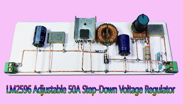
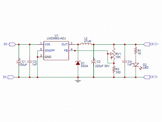
how to make DC - DC Step Down Power Supply Module, Adjustable 50A Step-Down Voltage Regulator
The LM2596S Adjustable DC-DC Step Down Module can step-down the input voltage to a range of 1.25 – 35V at up to 2A.
PACKAGE INCLUDES:
- LM2596S Adjustable DC-DC Step Down Module
KEY FEATURES OF LM2596S ADJUSTABLE DC-DC STEP DOWN MODULE:
- Compact size
- LM2596S converter IC
- Output voltage adjustment
- Output current up to 2A (see chart below)
- Input voltage range 3.5 to 40V
- Output voltage range 1.25 to 35V
DC-DC Step-Down converters (also known as ‘Buck’ converters) convert a higher voltage to a lower voltage while also stepping up the available current.
This DC-DC Step-Down converter is adjustable and capable of outputting a voltage in the range of 1.25 to 35V at a continuous current of up to 1.5A and short-term current of up to 2A with a maximum power output of up to 24W. The input voltage must be higher than the output voltage.
The LM2596S converter IC has over current and thermal limiting features built-in.
The board has 2 holes which can be used for mounting it permanently if desired using two small M3 screws.
Voltage Adjustment
The module has a multi-turn potentiometer for adjustment of the output voltage.
Turning the pot CW increases the output voltage while turning it CCW decreases the output voltage.
When first received, the pot is usually railed in the CW direction so the output voltage will be close to the input voltage. The pot will require multiple turns in the CCW direction before the output voltage starts to decrease.
The lowest output voltage is approximately 1.25V. The upper limit of the adjustment range will depend on the input voltage and is typically about 1.5V less than the input voltage. With a 12V input for instance, the upper output limit will be approximately 10.5V.
Module Connections
These are compact boards with input power applied to one end and output power available on the other end. With the silkscreen right-side up, the input will be on the left side.
Connections are solder type so wires or header pins will need to be soldered to the board to connect power. The pinout is not on 0.1″ centers, so they cannot be plugged directly into a breadboard. For light duty use on a solderless breadboard where not much current is being pulled, short M/M jumper wires can work to connect power by soldering one end to the board and using the other end to plug into the breadboard. For short term use such as to test the module, small alligator clips can be used to make the connections.
Input Power
- IN+ = Input voltage (3.5 to 40V)
- IN- = Ground for Input
Output Power
- OUT+ = Output voltage (1.25 to 35V)
- OUT- = Ground for Output
Note: The grounds on input and output side are in common. This is not an isolated supply.
OUR EVALUATION RESULTS:
You can find variations of these small DC-DC converters for sale in many places. Unfortunately the sellers typically just state the maximum specs of the switcher IC that is being used in the design without regard to the quality of the overall implementation and rate these assemblies at 3A.
To get maximum performance requires providing significant heat sinking for the switcher IC, using high quality low ESR electrolytic capacitors and using an inductor that can handle the maximum output currents. These assemblies fall a little short on all 3 of these points which requires derating of their specs as we do here.
Having said that, these modules do have a great price/performance ratio if they are used within their limits as outlined below and have proven very robust in our testing. Their weakest point is their output ripple which runs around 300mV on average. Not ideal for driving logic directly but works fine for driving a linear regulator, motors and similar applications. A filter capacitor on the output can also be used to help reduce the ripple.
The table gives some thermal results with an ambient temp of approx 25°C and the module operating at different input and output voltages and current loads of 1A, 1.5A and 2A.
In general at 1A, the module is very comfortably limping along. At 1.5A is it starting to get pretty warm but is still in a comfortable range. At 2A it is starting to get pretty toasty and in some cases too warm as indicated in red.
While this measurement is being taken on the converter IC, the capacitor and inductor thermals are tracking similarly. Electrolytic capacitor life in particular is directly tied to their operating temp. For long-term reliable use, I would not recommend running more than about 1.5A on this module. For short-term use like for breadboarding, you can pull 2A without any problems.
 Reviewed by Samnang Son
on
6:27:00 AM
Rating:


No comments:
Post a Comment